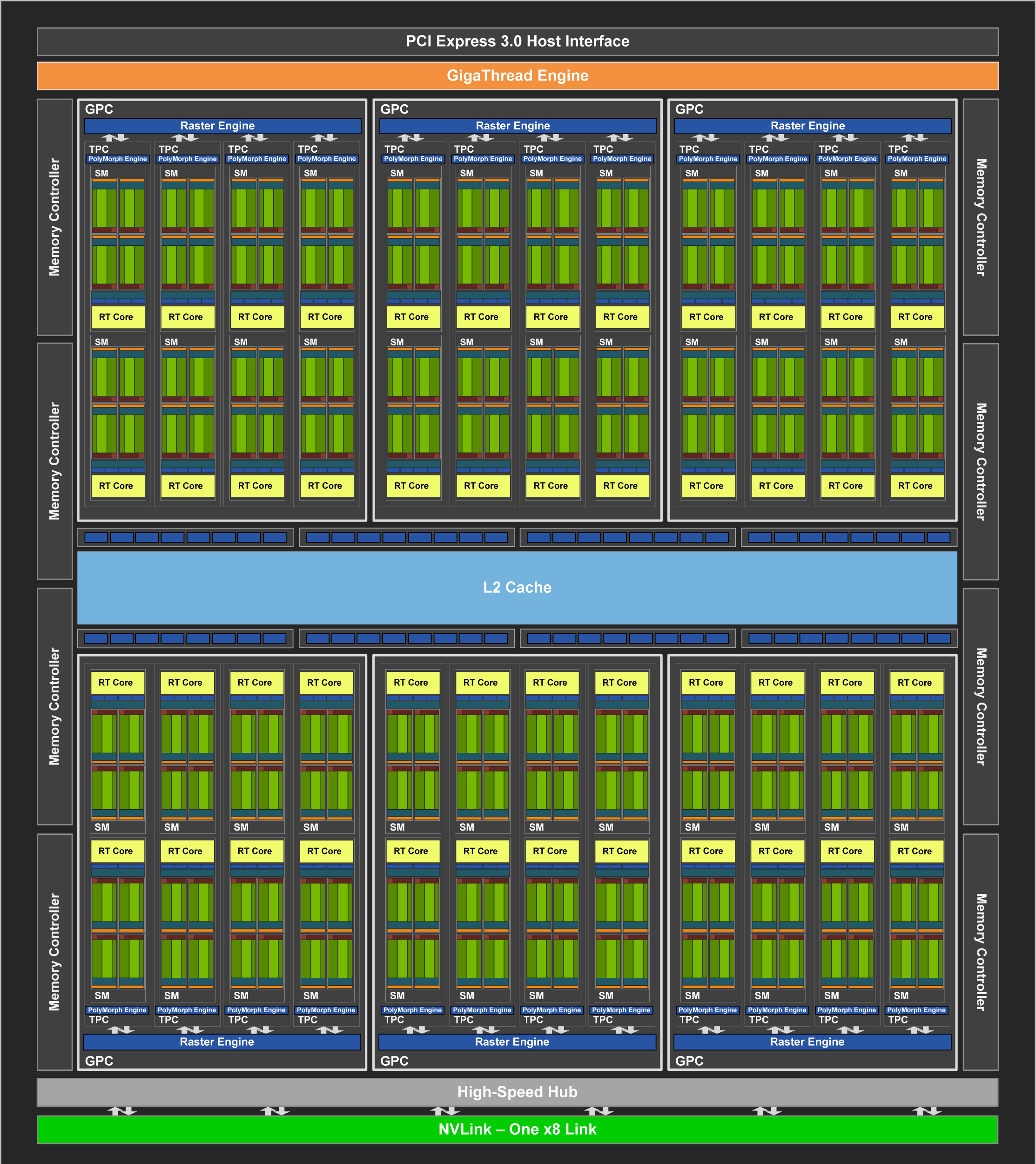
Turing Block Diagram
Superficially, the block diagram of the Turing TU104 chip (below) has a hierarchy very similar to that of the GV100. The 48 SMs are paired up into 24 Texture Processing Clusters, which are divided into 6 GPU Processing Clusters.


But the TU104 features a number of elements that are not found at all in a GV100, because each cluster or level in the hierarchy is home to a special type of processing unit that accomplishes a certain step in the graphics pipeline. The table below shows the special units that are associated with different blocks in the TU104 block diagram:
| Block Name | Associated Special Unit | Count in TU104 |
|---|---|---|
| SM | Ray Tracing Core | 48 |
| TPC | PolyMorph Engine | 24 |
| GPC | Raster Engine | 6 |
In addition, each Memory Controller has associated with it a set of 8 Render Output units (or ROPs, displayed near the L2 cache in the above diagram). Since there are 8 memory controllers, in all, the TU104 has a total of 64 ROPs.
For applications that just want to use the GPU to crunch numbers, these special graphics features have no particular importance, other than as an aid in understanding why the hierarchical arrangement of the SMs exists in the first place.
CVW material development is supported by NSF OAC awards 1854828, 2321040, 2323116 (UT Austin) and 2005506 (Indiana University)